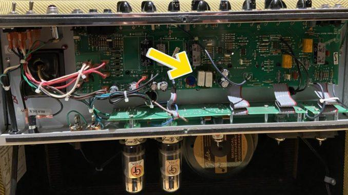
For those of you who love the warm sound of the Fender ‘57 Blues Deluxe Reissue blasts, balanced with its drive, presence, and spring reverb, you’ll be disappointed when it begins to cut out after long periods of play at higher than normal volumes.
The Blues Deluxe Reissue is a robust tube guitar amplifier well-suited for commercial or stage use. The reissue is as much a workhorse as its original incarnation which was introduced to the world in 1957, a great year for both guitar and automobile enthusiasts. Think Chevy ‘57.
The newer reissue version does great justice at mimicking its relic ancestor, but it’s not the same amplifier. While design has seen few changes in its history, its manufacturing process is not what it was nearly seventy years ago.
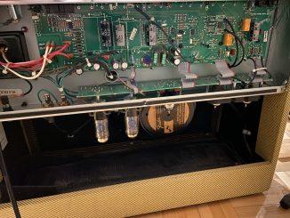
Today’s Blues Deluxe’s power resistors R78 and R79 are almost always the first components to degrade. Degrading eventually progresses towards failure. On the reissue construction, R78 and R79 are both 470 ohms ceramic 5 watt resistors, soldered directly to the printed circuit board. Over time, the heat these babies dissipate causes charring on the board and eventually, the power stage begins to cut out when driving the amp for a while. I’ve experienced this firsthand on my own amp, especially on the clean channel. For this reason, I haven’t really been able to enjoy the warm, creamy sounds when playing on this channel, as it begins to cut out within five to ten minutes of playing loud and bass-y.
I replaced the ceramic resistors with axial, wire-wound types of the same values (470 ohms, 5 watt, 10%). Keep on reading to know the steps I took last night to repair this issue once and for all. I ordered the resistors on Mouser and they were delivered within 48 hours.
WARNING: If you’re unfamiliar with high energy electronics, please contact a qualified technician. AC power enters the cabinet and voltages produced by the tubes are upwards of 350 volts and can be lethal, even when the amp is turned off.
Tools you’ll need
- #1 Phillips screwdriver
- #2 Phillips screwdriver
- Miniature flat screwdriver
- Long nose pliers
- Soldering iron (30-45 watts)
- Lead-free solder
- Solder sponge
- Desoldering pump
- Remove the back panel, by unscrewing the Phillips screws using a Phillips #2 type screwdriver.
- Remove the knobs with a small flat screwdriver and using a nut driver, remove all the chicken head pot knobs. Placing all the hardware in such a way that it goes to its original location is always good practice.
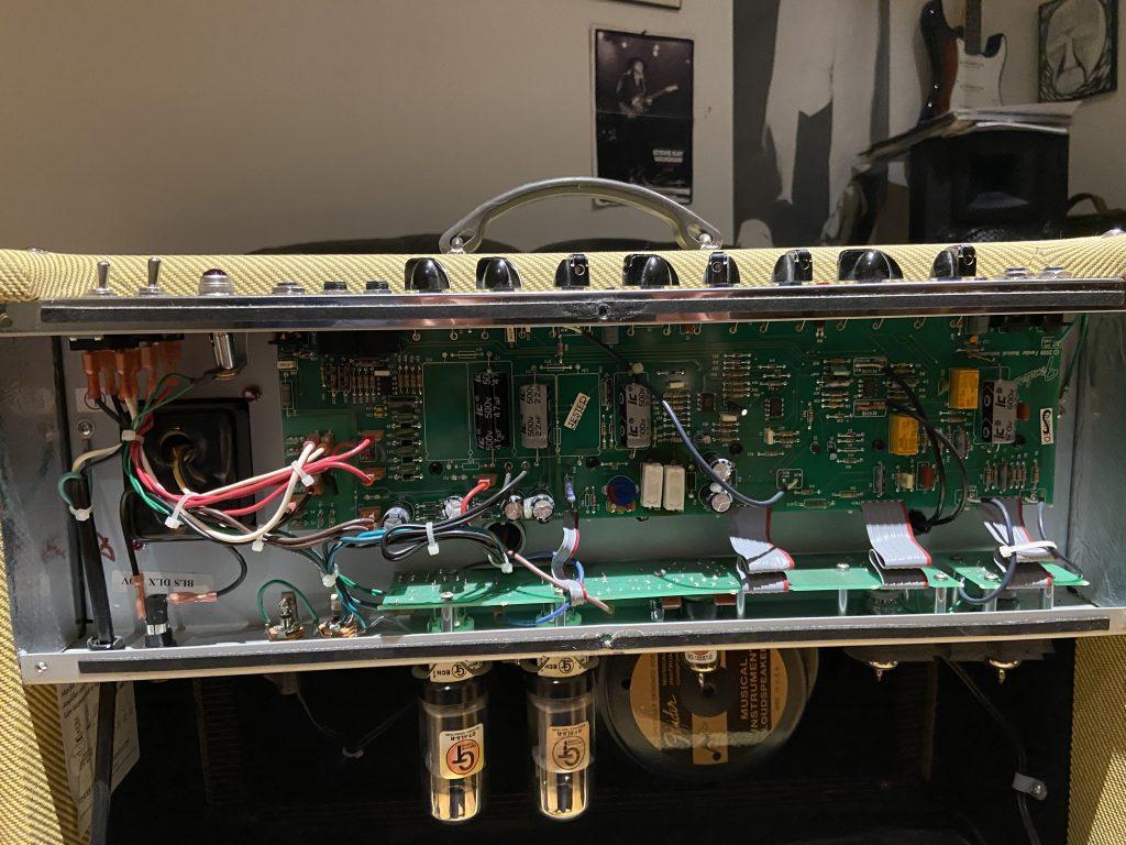
- Using a #1 Phillips screwdriver, remove the ground wire behind the printed circuit board on the right.
- Using the same screwdriver remove the six black screws which are securing the circuit board to the standoffs.
- Carefully remove the board by pressing downwards so the circuit board’s edge with the pots clear the openings. You’ll have to press on the cable bundles so be careful not to put too much stress when you lower the board and lean it outwards.
- When desoldering the old resistors, be sure to add enough solder to the solder pad, but be very careful not to heat the pad too much and lift it.
- Clear the solder pads so that the new resistor leads can be inserted. Keep the resistors off the board’s surface to ensure more adequate ventilation.
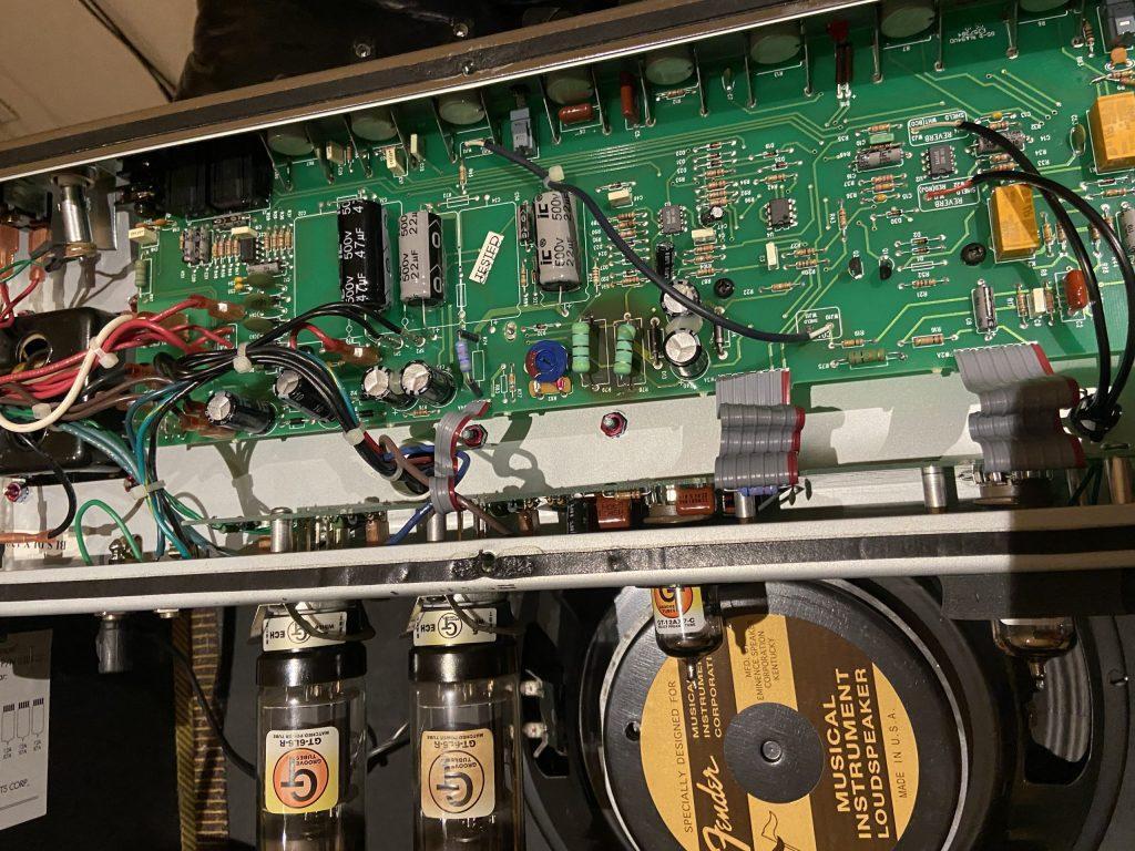
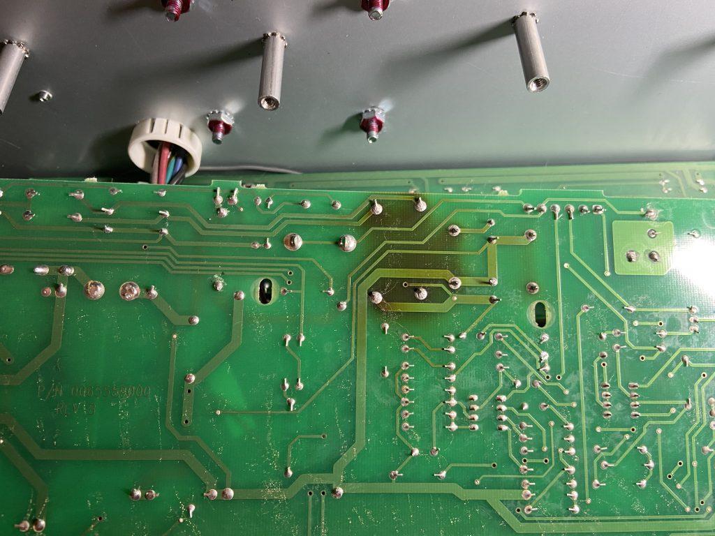
As for the darkened circuit board, you’ll just have to live with this. Don’t try to scrub or clean the charred surface as that will only increase the chance of doing further damage by lifting a solder pad or trace.


Be the first to comment